|
|
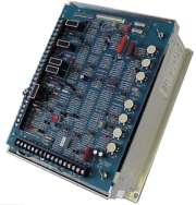 |
| MELLTRONICS 2600RG (262-80XX) |
HP |
INPUT
VOLTS
AC |
ARM
VOLTS
DC |
FIELD
VOLTS
DC |
100% DC
ARMATURE
CURRENT |
MODEL
NUMBER |
PART
NUMBER |
| 1/4 - 1 |
120 |
90 |
100 |
10 |
2600RG |
262-8000 |
| 1 1/2 - 2 |
120 |
90 |
100 |
20 |
2600RG |
262-8001 |
| 3 - 5 |
240 |
180 |
200 |
25 |
2600RG |
262-8001 |
| 5 - 7 1/2 |
240 |
180 |
200 |
38 |
2600RG |
262-8075 |
Customer Programmable:
- Input voltage 120 or 240 VAC
- Current range (Horsepower)
- Armature voltage feedback (90 or 180 VDC)
- Tach Feedback
- Torque or Speed Regulation
- IR Compensation (negative or positive)
- 10% reverse operation
- 50 or 60 Hz
- Accel/decel time range .2-4/2-30 seconds
- Ammeter full scale reading (150% or 200%)
GENERAL DESCRIPTION
The MELLTRONICS 2600RG is a high performance, regenerative DC motor control. Included are many standard features that are available only as options on many other single-phase regenerative drives. Accessibility to all important internal regulator points is provided by terminals on the control. This permits the MELLTRONICS 2600RG to be used in custom engineered applications, as well as in standard speed regulated applications. The MELLTRONICS 2600RG was designed to handle most single phase regenerative drive applications without the addition of external hardware and the need for costly, time-consuming engineering.
Three control models handle the entire 1/4 to 7 1/2HP range of applications. Drive current limit and inverse time overload protective circuits for rating within this range are calibrated by means of a jumper change on the main printed circuit board.
The MELLTRONICS 2600RG controls a DC motor's speed or torque by varying the DC voltage applied to the motor's armature. Because the control is regenerative, it can provide power to the load and return that power to the AC power line. Rectilinear phase control assures stable operation at low speeds and smooth transitions between motoring and regenerative modes (zero deadband).
The MELLTRONICS 2600RG is a versatile control. Simple jumpered programming allows the MELLTRONICS 2600RG to operate from either 120 or 240 volt AC input power at 50 or 60 Hz. Additional jumpers program the control to operate as either a speed regulator with armature voltage or DC tachometer feedback or as a torque regulator with armature current feedback. Two control models cover the entire 1/4 to 5HP range of applications. Drive current limit and inverse time overload protective circuits for ratings within this range are calibrated by means of a jumper change on the main printed circuit board. DC output current varies as a function of an input reference voltage in torque regulated applications. Changing the torque reference (potentiometer setting) results in a change in motor torque output.
The MELLTRONICS 2600RG control converts single phase AC input power to variable voltage DC output power. The DC output is applied directly to the DC motor armature. DC output voltage varies as a function of an input reference voltage in speed regulated applications. (Typically, this input reference voltage is provided by an operator adjustable potentiometer). Changing the speed reference (potentiometer setting) results in a motor speed change.
The MELLTRONICS 2600RG control is designed for use with either shunt wound or permanent magnet DC motors. A fixed voltage unregulated DC source is provided for connection of the motor field in wound field applications. Included in the MELLTRONICS 2600RG control are many built-in features not available on competitive units. Motor field economy and separately adjustable rates of acceleration and deceleration are included on all units. If desired, the built-in accel-decel control ramps can be by-passed completely by a jumper change on the control. Current compounding can be added to the speed regulator by changing another jumper position. Current limit is normally set by a potentiometer located on the main printed circuit board, but if desired, it can be adjusted using a remote mounted potentiometer or a customer supplied voltage signal. An output signal is available for use with one of the MELLTRONICS 2600RG ammeter kits to provide an indication of drive output current without the addition of an ammeter shunt. On occasion, customer requirements may dictate that the operator's devices be mounted on the door of the enclosure.
STANDARD FEATURES
- Circuit Board Indicators - Light emitting diodes (LEDs) of the main circuit board indicate: DC overload, Field Loss, Instantaneous Over-current Trip, Run Mode, Jog Mode, SCR's Being Gated, Fault Trip
Circuit. Protective circuits are designed to quickly shut the drive down and provide a visual indication whenever a DC overload, field loss, or instantaneous over-current condition occurs. This fault trip circuit prevents restart. It must be reset before the drive can run again.
- Solid State Full Wave Power Bridge - Uses generously rated power semiconductors for maximum reliability and long life.
- Isolated Control Circuitry - Provides complete isolation of the control and regulator circuitry from the AC power bus for protection in the event of a ground fault. The ammeter, speed potentiometer, and tachometer are not at line potential. Complete system capability is also possible without additional isolation accessories.
- Power Supplies - Each MELLTRONICS 2600RG contains and internal 115 VAC power supply to power the DC loop contractor and drive logic relays. Internal ±24 VDC, ±15 VDC and a regulated ±10 VDC power supply are also included.
- Ammeter Output - Motor current can be indicated with the simple addition of a remote meter.
- Field Economy - Insures longer life for wound field DC motors. May be easily bypassed or time delayed to meet specific application requirements.
- Double Break DC Armature Loop Contactor - Full rated and fully sequenced contactor assures positive disconnect of DC motor when the stop push button is pushed or whenever and under-voltage condition occurs.
- Remote current Limit - Available by the simple addition of a potentiometer or DC voltage input.
- Negative IR Compensation- Available by jumper connection. Allows use of control in jumper applications.
- Current (torque) Regulator - 1% accuracy armature current regulator allows the operator to control motor torque instead of speed.
- Speed Regulator - 2% accuracy using armature voltage feedback with IR compensation or 1% accuracy with tachometer feedback. Regulation may be improved by selecting the proper motor mounted tachometer.
- Separately Adjustable Linear Accel/Decel Control - Two ranges: 0.2-4 seconds or 2-30 seconds.
- Rectilinear Phase Control - Improves performance at low speed and near zero load.
- Inner Current Loop Regulator - Inherent high band width capability for fast response.
- Quadrant Lockout - May be selected by jumper programming to prevent forward or reverse motoring in certain applications.
- AC Line Filter and Transient Voltage Suppression Network - Eliminates interaction between other drives or AC equipment.
- Reactors. Snubber Networks - Prevents SCR DV/DT failures due to line spikes and transients. Provide DI/DT protection during SCR turn on and aids in SCR turn off during SCR commutation, minimizing the effects of AC power notching.
- SCR Trigger Circuits - Pulse transformer isolated, hard firing, high frequency "burst" type pulse train output from individually grated oscillators insures SCR conduction regardless of the effects of the notching or incoming AC power line.
- Standard Adjustments - Max, speed, zero bias, acceleration time, deceleration time, IR compensation, current limit, jog speed, velocity stability, speed rate and current stability.
- Jog at Preset Speed - Separately adjustable from zero to plus or minus 30% of base speed.
- Dual Frequency Operation - Controls may be operated from 50 to 60 Hz power supplies by simple jumper change.
- Exclusive Static Adjustable Current Limit - Allows static setting of the desired current limit value without applying DC power and without a connected output load whenever the optional test meter in connected.
- Common Control Circuit Boards - 262-8000 and 8001 MELLTRONICS 2600RG series controls utilize the same PC board regardless of HP, voltage, frequency, or control mode.
- DC Overload (Armature) - Senses over-current condition with inverse time shutdown.
- Field Loss Protection - Provides protection against runaway due to loss of motor field by shutting down the drive.
- High Speed Current Limiting SCR Semiconductor Fuses - Provide the utmost in fuse coordination and protection of the SCR's and motor with positive circuit clearing on both AC and DC faults.
- Instantaneous Over-current Protection - Senses armature fault current quickly to protect both semiconductors and motors against damaging current levels.
OPTIONS
- Test Meter - This modification consists of a digital panel meter and multi-position selector switch. It provides the capability to monitor nine critical drive parameters. The test meter kit plugs into the regulator PC Board on the 2600RG. It is an ideal addition to the control as an aid in troubleshooting and start-up.
- Ammeter Kit - The 2600RG control includes circuitry to drive an external ammeter without the addition of an ammeter shunt. This external meter can be calibrated in either percent load or in amperes.
(Additional Options - many additional options are available to meet specific drive application requirements including: reversing, dynamic braking, process signal follower, specific logic, auxiliary control, field weakening, and isolation transformers - Contact Melltronics Industrial for details.)
SPECIFICATIONS
Service Conditions:
- Rated Voltage Input: 120 or 240 VAC (±10%) 1 Phase
- Rated Voltage Output: 90 or 180 VDC
- Frequency: 50/60Hz (±2Hz)
- Ambient Temperature: 0-40° C (32° F to 140° F)
- Altitude: Sea Level to 3300 Feet
- Efficiency: Power unit 98% or better depending on selected rating. Drive system 82% or better depending on selected rating.
- Load Inertia: Not more than motor inertia when referred to motor shaft.
- Power Factor Corrected AC Line: Drive installation on power factor corrected AC lines should be avoided where possible.
Performance:
- Control Speed Range: 20:1 for basic control. May be extended to 200:1 by modification.
- Speed Regulations:
For a 95% load change:
Voltage Regulated: 2-5% of max. speed. Speed regulated 1% of max. speed with any DC tachometer.
For all other variables:
Voltage Regulated: changes up to 15% of top speed can result from temperature variations, voltage; and frequency variations, and drift.
May be modified to achieve: 0.1% due to 95% load change and 0.15% due to all other variables.
Adjustments:
- Maximum Speed: 70 to 130% rated speed
- Acceleration Time: 0.2 to 30 sec.
- Deceleration Time: 0.2 to 30 sec.
- Jog Speed: 1 to 30% rated speed
- IR Compensation: 0 to 10% rated voltage
- Current Limit: 1 to 150% of selected range
Control Power:
- Voltage (Relay Logic): 115 VAC
- Spare Capacity: 5 VA
Input Signal Requirements:
- ±10 VDC at 1mA (nominal) for max output
Speed Potentiometer:
- 500 Ohms, 2 Watts
Field Data:
- Voltage: 100 VDC with 120 VAC input 200 VDC with 240 VAC input
- Current: 3 amperes max.
|
| MOUNTING DIMENSIONS FOR CHASSIS ES2600RG |
|
REV DATE: 8/15/2006
©2020 SCR Controls, Inc.
3479 Gribble Rd., Matthews, NC 28104
PO Box 2368, Indian Trail, NC 28079
email:
|
|
|
This sight is viewed best viewed with the latest versions of Netscape,
Internet Explorer and Chrome. |
A. Manufactured items:
MELLTRUM (SPECTRUM REPLACEMENT) ES100A ES125A ES150A ES150ARG ES200A ES200ARG ES222 ES2300RG ES2600RG ES2700 2400-8000 2400-8001W 2450-8000W
2450-8001W 2450-8010W 2450-8015W
EDDY CURRENT CLUTCH 1235 367 FOCUS 2 FOCUS1 FOCUS 1 REPLACEMENT BOULIGNY MARK ANDY SECO BALDWIN ENKEL CUSTOM AUTOMATION SYSTEMS MULTI DRIVE SYSTEMS ERC REPLACEMENT.
|